Parameters
- Interface with IPC: Standard MiniPCIe interface;
- Communication mode with IPC: USB2.0 pin in MiniPCIe interface;
- Power supply mode: MiniPCIe interface 3.3V power supply, power consumption 200mA;
- Number of CAN channels: 2-channel isolated CAN interface;
- CAN TTL signal can be switched to the second function IO, which is convenient for designing CAN transceiver circuit;
- CAN supports CAN2.0A and CAN2.0B protocols, which conforms to ISO/DIS 11898-1/2/3;
- CAN Baud rate: Programmable and arbitrary setting from 5 Kbps to 1 Mbps;
- Maximum frame flow: Single channel can reach 14,000 frames/s (1M Baud rate, standard remote frame);
- CAN channel adopts electromagnetic isolation and DC/DC power isolation, and the isolation voltage is 2500VDC;
- EMC grade of CAN interface: Contact discharge ±4KV, group pulse ±1KV;
- Support Win2000, WinXP, Win7 and Win8 operating systems and Linux2.4, Linux2.6 operating systems;
- It can be used in the environment with safety and explosion-proof requirements;
- Installation method: Standard MiniPCIe card slot, compact size, plug and play;
- Operating temperature: -40℃ ~+85℃;
- Standard MiniPCIe board dimension: 30mm (width) * 50.95mm (length).
CAN interface form:
The internal jumper wire of DB9 interface led out through the anti-seismic terminal selects 120 Ω terminal resistance.
| Port | Pin | Name | Function |
|---|---|---|---|
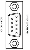 | 1 | NC | Unused |
| 2 | CAN_L | CAN_L signal line connector | |
| 3 | CAN_GND | CAN isolated ground, no connection required | |
| 4 | NC | Unused | |
| 5 | SHIELD | Shielded wire connector (FG) | |
| 6 | CAN_GND | CAN isolated ground, no connection required | |
| 7 | CAN_H | CAN_H signal line connector | |
| 8 | NC | Unused | |
| 9 | NC | Unused |
MiniPCIe interface definition:![]()
| Port | Pin No. | Signal name | Description |
|---|---|---|---|
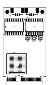 | 1 | nWAKE | NWAKE signal/ pull-up by default |
| 22 | nRESET | NRESET signal/unused | |
| 17 | TD0_REV | CAN0 TXD second function IO* | |
| 19 | RD0_REV | CAN0 RXD second function IO* | |
| 37 | TD1_REV | CAN1 TXD second function IO* | |
| 39 | RD1_REV | CAN1 RXD Second Function IO* | |
| 36 | USB_D- | USB_D- | |
| 38 | USB_D+ | USB_D+ | |
| 2、24、52 | 3.3V | Power Supply | |
| 9、15、18、21、26、27、29、34、35、40、50 | GND | Ground |
* Description of pin switching of the second function
When you need to design the CAN transceiver circuit or improve the protection level of the CAN signal line, you can connect the TTL signal of the second function pin of CAN signal to the base plane through the Mini PCIe reserved pin, and design the CAN transceiver circuit to improve the flexibility of the system.

The second function pin of CAN signal is switched through R24. R24 is soldered by default, and the system adopts the default onboard CAN isolation transceiver. When R24 is removed, the second function pin of CAN signal is enabled automatically when the system is powered on.
Accessories list
The accessories list is for reference only. Please refer to the material object.
| MiniPCIeCAN-II | ||||
|---|---|---|---|---|
| SN | Name | Quantity | Unit | Remarks |
| 1 | MiniPCIeCAN-II board | 1 | Piece | |
| 2 | MiniPCIeCAN-PACK board | 2 | Piece | |
| 3 | Copper column | 2 | Piece | |
| 4 | Certificate of conformity | 1 | Piece | |
| 5 | Metric screw | 2 | Piece | |
| 6 | Nut | 2 | Piece | |
| MiniPCIeCAN-2E-U | ||||
|---|---|---|---|---|
| SN | Name | Quantity | Unit | Remarks |
| 1 | MiniPCIeCAN-2E-U board | 1 | Piece | |
| 2 | MiniPCIeCAN-PACK board | 2 | Piece | |
| 3 | Copper column | 2 | Piece | |
| 4 | Certificate of conformity | 1 | Piece | |
| 5 | Metric screw | 2 | Piece | |
| 6 | Nut | 2 | Piece | |
